3-way to PICV conversion
Replacing 3-way valves so chilled water is no longer bypassed back to the return, which is one of the most common causes of low ΔT.
 GrüntekENERGY SOLUTIONS
SOLUTION · 04
Conversion of 3-way and 2-way valve systems to pressure-independent control valves (PICVs) on AHUs and FCUs, with selection, installation, commissioning and flow verification, so the chilled-water network holds its design ΔT at part load with reduced pumping. We supply and install the full Danfoss PICV range for chilled-water buildings, from FCUs and AHUs to ETS heat exchangers.
WHAT WE DELIVER
Conversion of 3-way and 2-way valve systems to pressure-independent control valves (PICVs) on AHUs and FCUs, with selection, installation, commissioning and flow verification, so the chilled-water network holds its design ΔT at part load with reduced pumping.
Replacing 3-way valves so chilled water is no longer bypassed back to the return, which is one of the most common causes of low ΔT.
Balanced 2-way systems work at design conditions but drift at part load. PICVs hold each unit on its required flow whatever the pressure.
Danfoss PICVs and actuators selected for each unit from its design flow, from small FCU valves to AHUs and ETS heat exchangers.
Phased floor by floor, using techniques such as pipe freezing where a section has to be isolated, to keep disruption to a minimum.
Flow settings are set and verified at each unit, and the results are documented at handover.
Once flows are under control, the pump differential-pressure setpoint can be reviewed so the pumps slow down at part load.
SEE THE DIFFERENCE
Switch between a 2-way valve system balanced with DRVs and PICVs, at full and part load, to see what happens to flow, ΔT and the pump. Most buildings spend most of the year at part load.
2-way valves with DRVs · Part load
At part load, the 2-way valves close and the pressure across each branch changes. Flow through a valve follows Q = Kv × √ΔP, so units near the pump see extra pressure and over-flow, while units at the end of the riser under-flow. The DRV settings only hold at design conditions, so ΔT drops and the pump moves more water at a higher pressure than the load needs.
Q = Kv × √ΔP
At part load
2-way + DRV → PICV
Illustrative model of one riser with a typical mix of AHUs and FCUs, both options on a variable-speed pump, using Q = Kv × √ΔP, pump affinity laws and simplified coil behaviour. It is not a savings estimate. Every building is different, so we measure yours.
RELATED WORK
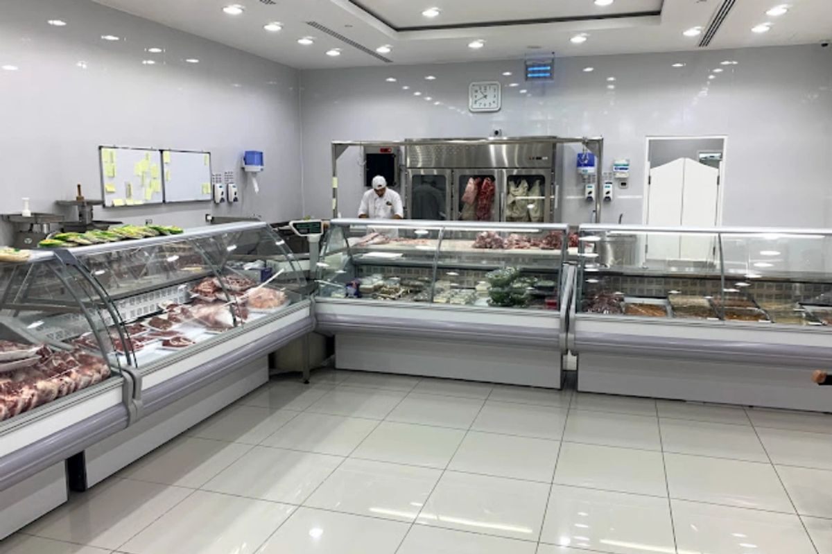 Hydronics
Chilled water network hydronic calculations
 Hydronics
Delta-T study
 Hydronics
Chilled water network hydronic calculations
 Hydronics
Delta-T study
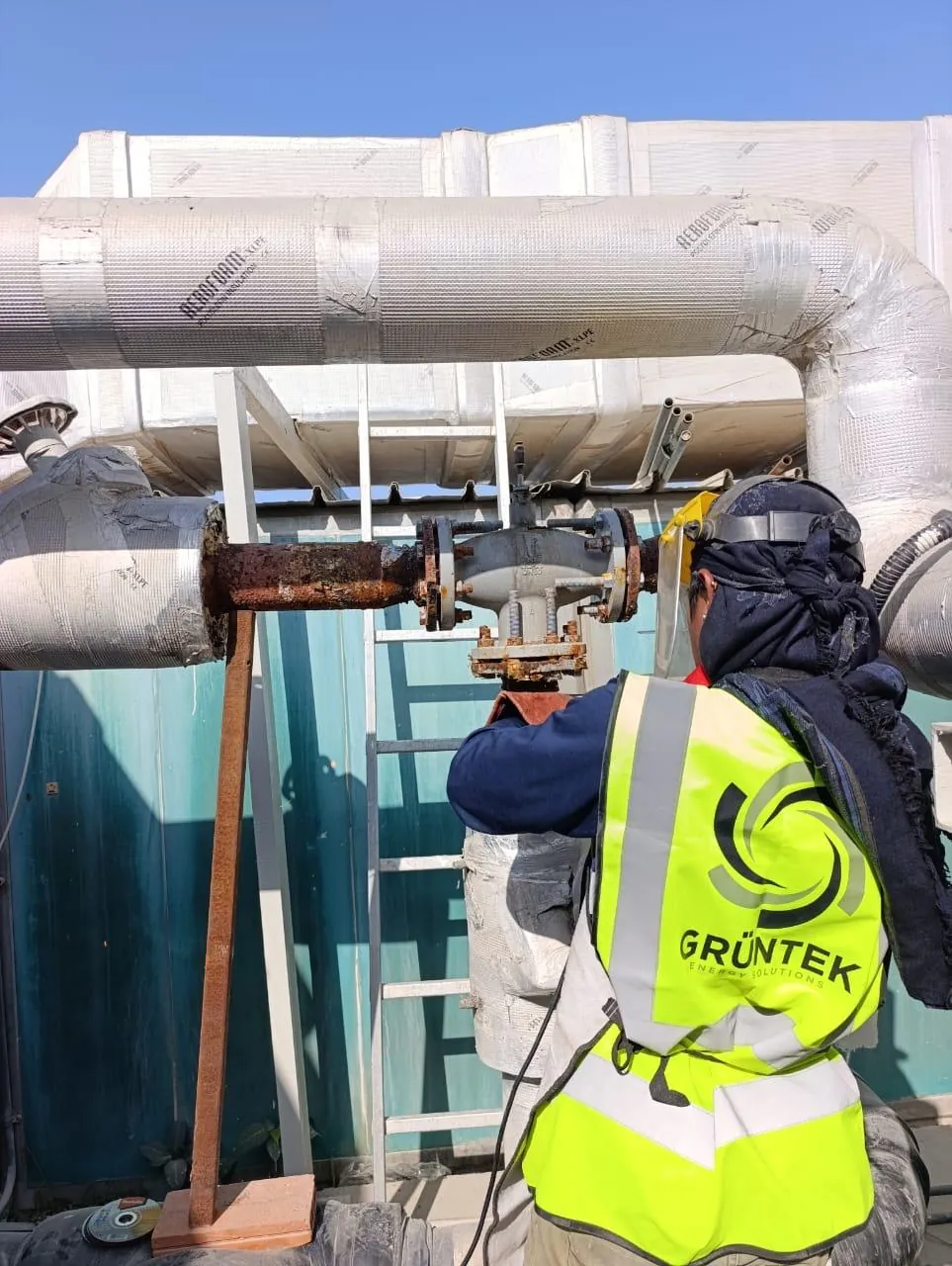 Optimisation
PICVs & HVAC energy-management controls
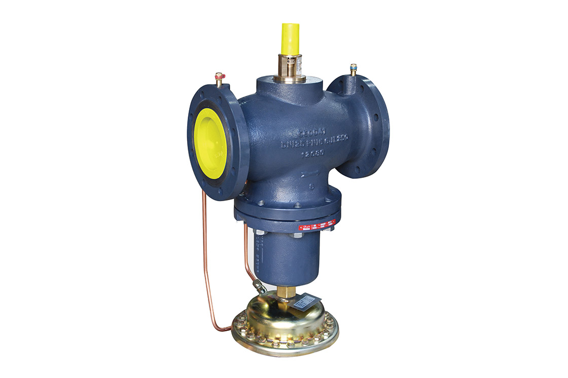 Supply
Danfoss PICV & actuator supply
PRODUCTS & PLATFORMS
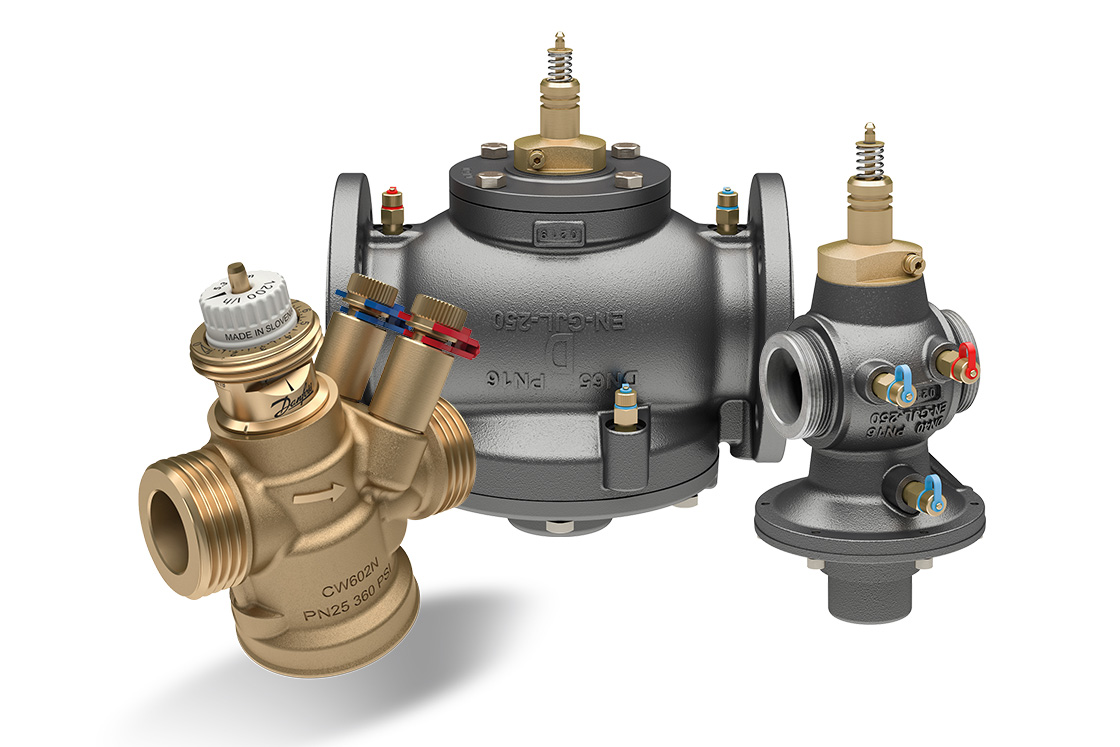

Danfoss products for your project.
Product details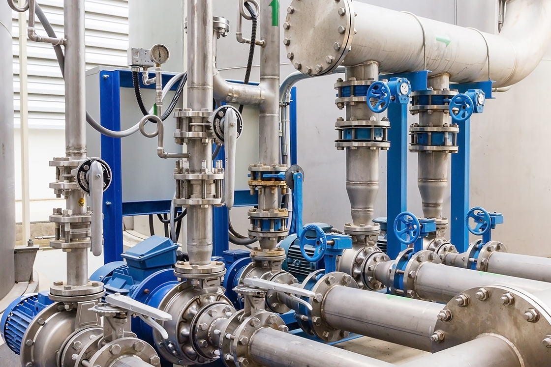
Equipment for pumping and fan systems.
Product detailsComprehensive and non-comprehensive AMCs for chillers, condensing units, HVAC, ETS, BMS and metering.
FAQ
A pressure-independent control valve holds each unit at the flow it needs, whatever the pressure in the pipework. A system balanced with 2-way valves and DRVs performs well at full load, but its settings only hold at design conditions. At part load, flow through each valve follows Q = Kv × √ΔP, so as pressures shift some units over-flow and others under-flow. That lowers ΔT and makes the pumps move more water than the load needs. PICVs keep every unit on its required flow with reduced pumping.
Yes. They improve balance and ΔT on their own, and the pumping benefit is largest when the pumps also run at variable speed. We assess the pumps and controls as part of the survey.
3-way valves send unused chilled water straight back to the return, which lowers ΔT at part load. Converting them to PICVs, together with variable-speed pumping, is usually one of the first measures we look at.
It addresses one of the main causes of low ΔT. Whether it is enough on its own depends on the building, so we measure first. See our Delta-T rectification plans.